Xu Shuang Ankerui Electric Co., Ltd., Shanghai Jiading 201801 0 Preface (1) Miscellaneous firefighting facilities A large number of fire-fighting products have been set up in modern large-scale buildings, public gathering places and high-rise buildings: automatic repertoire systems, automatic sprinkler systems, fire-fighting broadcasting, telephones, smoke control systems, electrical fire monitoring systems, gas fire extinguishing Systems, fire extinguishing systems, emergency lighting systems, fire elevators, shutter doors, etc. (2) Potential for power out of control Fire safety depends largely on the quality of fire fighting equipment. The proper operation of the fire fighting system and related fire fighting linkage equipment depends on the working status of its power supply. All along, failure of fire control equipment caused by the loss of control of equipment power has resulted in frequent fire incidents, especially during periods of intense social power supply, poor equipment quality, and weak safety awareness. This problem is even more prominent. Mainly suitable for some large public buildings, densely populated places: 1) Large-scale disease hospitals (ward building, out-patient building), theaters, halls, auditoriums, gyms, department stores, and shopping malls; 2) Exhibition buildings, high-class hotels, financial and financial buildings, telecommunication buildings, and high-grade office buildings; 3) Civil buildings such as underground railways, railway stations, tunnels, bus stations, cinemas, and auditoriums. 1 system structure The AFPM100 fire-fighting equipment power monitoring system adopts a three-layer structure networking mode of the power equipment + monitoring module + system host, thereby simplifying the system structure design. The entire monitoring system is full-featured, safe and reliable, with accurate detection and high cost performance. The system uses RS485 network communication internally and provides Modbus-RTU communication protocol externally to meet the connection of other standard systems. 2 system function (1) Monitoring alarm (2) Fault alarm (3) Control output (4) Self test (5) Alarm record (6) Operation classification 3 Design Cases 3.1 System Wiring Diagram (1) Network topology of small and medium-sized monitoring systems Module AFPM-□ is a sensor (monitoring module). The monitor (host) can receive and display the operating status of the monitored fire-fighting equipment power supply and the relay's working status. (2) Large-scale monitoring system network topology This system is used when there are many buildings or field facilities and needs to be divided into multiple areas. 3.2 Design Considerations (1) Description of power supply and communication cable 1 The communication line between the monitoring host and the detector adopts the bus type (hand-in-hand) connection mode; 2 The diameter of the communication line between the host computer and the module should not be less than 2x1.0mm cable; 3 detector power line is not less than 2x 1.5mm. (2) Installation location 1) Monitoring host 1 monitoring host installed in the fire control room; 2 It is dedicated to the power supply monitoring of fire-fighting equipment and installed independently. It cannot use the monitoring of other functions, and does not share the equipment with other systems to ensure the stability and safety of the system; 3 host dedicated power supply AC220V provided by the fire power. 2) Detector Installed in a special cabinet (box) near the power supply for the fire-fighting equipment on the monitored side. under special condition. Can be installed in the power distribution box of the monitored fire protection equipment power supply. (3) Configuration of the detector 1) The setting of the detector should be set at the end; the power of the fire-fighting equipment monitored by the detector should include the fire-fighting facilities in the following table; 2) The system's voltage sensor and current sensor should be set so that the power supply status of the entire fire protection system can be displayed on the monitor or in the fire control room in real time. It should be set in the following locations; the output terminal of the power distribution cabinet for the main power supply and fire power supply for the fire protection equipment within the building; the dual power input and output terminal for the fire protection electrical control device (including the water pump controller, fan controller, etc.) The output terminals of the fire-fighting equipment power supply devices (DC power supplies for each fire-fighting equipment) installed in each fire prevention zone; the output terminals of the power distribution box for fire-fighting equipment; the eager end and output end of emergency power supply for fire-fighting equipment; emergency The output terminal of the lighting distribution box; the input and output terminals of the emergency power supply for the centralized power type fire emergency luminaires; the equipment of the multiple main power supply should monitor the input terminals of each main power supply circuit. 3) The operating status of the following fire-fighting equipment independently provided by the fire control room is not shown on the fire alarm controller or fire-fighting linkage controller. A voltage sensor or a current sensor should be installed at the output of the power supply. . Electrical fire monitoring equipment; Combustible gas controllers; Fire shutter controllers; Gas fire control controllers; Linear fiber-optic heat detectors; Air sampling smoke detection detectors; Transmission equipment; Fire display panels; Other fire protection equipment. 4 Equipment List No. name Model, specification unit Note 1 Power Meter AFPM power monitoring module AFPM3-2AV station Ankerui AFPM power monitoring module AFPM1-AV station Ankerui total 2 Monitoring Center duty room Fire power monitoring equipment Acrel-AFPM wall-mounted set Ankerui Fire power monitoring equipment main components display board AFPM100 Piece Ankerui Control board AFPM100-P Piece Ankerui Panasonic UPS battery 12V24Ah(165*125*175) Section Matsushita Thermal printer RD-E32-485-24V (with Chinese font library) station Switching power supply TPC-H180SBAT only Auxiliary materials set total 3 Engineering Materials Communication cable ZR-RVSP 2*1.0 km power cable ZR-RVV 3*1.5 Meter Engineering materials Towboards, conversion lines, lines, signs, etc. set total 4 Construction and commissioning Communication cable laying Meter Instrument communication line connection only Instrument communication debugging only Comprehensive debugging People/day Equipment transportation costs item training fees item 5 Concluding remarks Implement the two national standards of "General Technical Requirements for Fire Control Room" and "Fire Control System for Power Supply", promote the application of "Fire Equipment Power Supply Monitoring System", comply with "The Opinions of the State Council on Strengthening and Improving Fire Protection Work," and "The Fire Department". Promote the development of more stringent fire safety standards in big cities." Implement the spirit of stricter fire safety standards. Not only provides a technical basis for the actual use of the fire protection department's law enforcement supervision and design and construction units, but also takes the lead in realizing a positive effect of effectively reducing the incidence of fire fighting equipment, building fire hazards, and protecting people’s lives and national property safety. The system realizes effective real-time monitoring in the fire control room, and displays various technical requirements for the working status of the power supply and standby power supply of each fire-fighting electrical equipment, and is applicable to new, expanded and rebuilt industrial and civil buildings. The system plays an important role in ensuring that the construction fire-fighting facilities are in good condition, improving the fire-fighting safety management level of all units, detecting the failure of fire-fighting equipment in a timely manner, and preventing and reducing fire hazards. references: [1]The application of fire-fighting equipment power monitoring system in the field. Wang Lei, Yao Shaojun. Electrical & Intelligent Buildings, 2013.11 [2] Ankerui Electric Co., Ltd. Product Selection Manual 2013.1. [3] Zhou Zhongzhong, ed. Smart grid customer end power monitoring and power management system product selection and solution IV. Beijing Machinery Industry Press, 2011.10 About the Author: Xu Shuang, female, undergraduate, Ankerui Electric Co., Ltd., the main research direction for the design of electrical fire monitoring and fire protection equipment power monitoring, mobile phone QQ "Atlas of Design and Application of Fire-fighting Equipment Power Monitoring System" (atlas number: ACR13CDX801) is edited by Ankerui Electric Co., Ltd. This atlas combines the characteristics of the AFPM series fire-fighting equipment power monitoring system and meets the requirements of electrical design specifications. The object monitors the normal use requirements of the fire-fighting equipment power supply so as to prevent the fire-fighting equipment from working normally when a fire occurs. The Atlas was compiled by the Honorary Chairman of the Electrical Engineering Committee of the Yunnan Civil Engineering Society, the Director of the Yunnan Provincial Architectural Design Institute Deng Zhao, the Vice Chairman and Secretary-General of the Hunan Electric Design Information Network, and the Chief Engineer of Hunan Provincial Architectural Design Institute. Liang Zhichao's review. The Atlas is applicable to the design and application of fire protection equipment power supply monitoring systems for 220V/380V power supply and distribution systems in new, expanded and rebuilt industrial and civil buildings and general industrial buildings, and includes the selection and installation of system equipment. Buildings with special requirements must be selected in combination with the actual conditions of the project. If you need an atlas, please provide your organization's name, department, address, zip code, contact person, contact telephone number, email address, fax, email@qq.com or QQ to Ankeru Xu cream engineer, Ankerui Electric Give away. Vehicle Greases,Automotive Grease,Automotive Lubrication,Car Wheel Bearing Grease Hangzhou Xingang Lubrication Technology Co., Ltd. , https://www.newlubes.com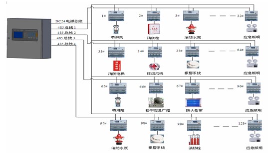

When the transmission distance is greater than 500m, a repeater is added. The 1-in. repeater occupies 1 sensor (monitoring module) address. The repeater's AC220V power cable is 3*1.5mm^2. It consists of on-site fire power or fire control room. Monitor (host) provided.
The transmission mode is RS485 bus, which is represented by A/B in the figure. The cable shielding layer should be reliably connected with the protection ground of the monitor (host).
Each type of sensor (monitoring module) sets the communication address with the monitor (host) via a code switch.
According to the engineering needs, a 120Ω-10KΩ/1W matching resistor should be connected at the most remote sensor (monitoring module) on the communication line to improve the communication stability.
The general power monitor (host) has 4 output circuits and each circuit can connect 32 sensors (monitoring modules). Special loops can be extended in special cases. 
Each zone monitor (host) can collect 128 sensors (monitoring modules), which can be expanded in special cases.
The main power supply for the monitor (mainframe) is AC220V. The standby power supply can be provided on site or on site.